Enquiry
We appreciate each customer and we are proud that 60% of clients come back to work with us again.
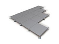
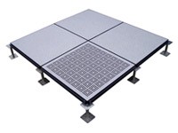
The raised access floor system shall consist of 600mm x 600mm x 34mm modular steel cement panels/cementitious panels/ cement filled panels as manufactured by ALTAIR. The panels should be interchangeable with other panels except where cut for specific purposes.
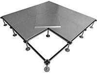
The floor is to be supported by a steel understructure consisting of an adjustable pedestal assembly with a finished floor height measured from the slab to finished top of the panel.
The manufacturing of the raised access floor components shall be under the stringent ISO quality management system. All structural access floor components shall be supplied by one manufacturer to ensure compatibility with ISO and maintain the standards.
Method for testing concentrated, ultimate and rolling loads of access floor panels shall be in accordance with international standards and procedures such as CISCA and shall be performed by an independent testing laboratory.
Installation of the raised access floor shall be approved by the general contractor, before other trades are involved to maintain the integrity of the installed floor system. Traffic shall not be permitted on any floor area for at least 48 hours allowing for the pedestal adhesive to set.
The successful sub-contractor must submit the following documentation within six months after adjudication of the tender or by negotiation.
From the approved testing laboratory, showing compliance with the requirements of the load performance table or specified design loads.
Systems and components data sheets fully describing and specifying the performance of components and the overall system.
General contractor shall provide a dry, secure storage and clean sub-floor which is free of dust, construction debris, and items from other trades during the installation of the access floor.
Materials shall be delivered in original, unopened packages clearly labelled with the manufacturer’s name and item description. Material packages shall be distributed around the area where they will be used to avoid overstressing the sub-floor and to facilitate installation.
The building shall be enclosed and the temperature shall be maintained between 10°C and 30°C and max. 75 % R.H.
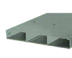
The panels shall be steel cement /cementitious /cement filled of size 600mmx 600mm x 35mm and AL800 /AL1000 / AL1250 model, and consist of structurally rigid cell assemblies fabricated entirely from non-combustible components. They shall consist of a flat steel top of thickness 0.8/1.0/1.2mm resistance welded in minimum 100 locations to steel bottom section of 0.7/1.0/1.0mm. The exterior surface of the access floor panel shall be protected from corrosion by a process of cleaning, phosphating, and coating with an electro-statically applied rust resistant and conductive polyester powder coating paint to a thickness of 60 microns. The panel shall be capable of supporting the design load with a minimum safety factor of 3 at the weakest point of the panel, based on ultimate strength of the material.
The core interior of the panel should be filled with non-combustible cementitious compound, to support no less than 80% of the top skin or surface of the panel.
The panels shall be either supplied bare, coated with an electro-statically applied rust resistant and conductive polyester powder coating paint to a thickness of 60 microns, or with a factory finish option as per architectural recommendations. Vinyl finishes to be 1.5mm anti-static or conductive; HPL finishes to be 1.0mm anti-static.
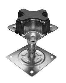
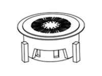
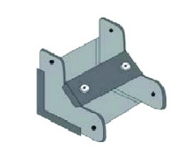
The Cross-Head understructure system shall consist of an electro-galvanized and factory assembled pedestal base, Galvanized steel cruciform shape pedestal head, with a black conductive pvc gasket. The system shall be capable of supporting an axial load of not less than 32.00kN for a finished floor height of 75mm to 300mm. The pedestal assembly shall be specific to the Cross-Head understructure system as manufactured by ALTAIR.
The pedestal base should consist of a 100mmx 100mm x 2.0mm thick electro-galvanized steel base plate welded to a 19.0mm outside diameter electro-galvanized steel threaded rod.
The pedestal head shall consist of a 71 m mx 71 mm cruciform electro-galvanized steel composite head with a material thickness of 3.0mm, threaded into an electro-galvanized threaded tube of 19.0mm outside diameter. A black rubber conductive gasket is placed on the cruciform head and is an integral part of the system
A corrosion resistant 9mm deep electro-galvanized nut shall be provided and shall allow for adjustment of the pedestal assembly over a minimum range of 50mm.
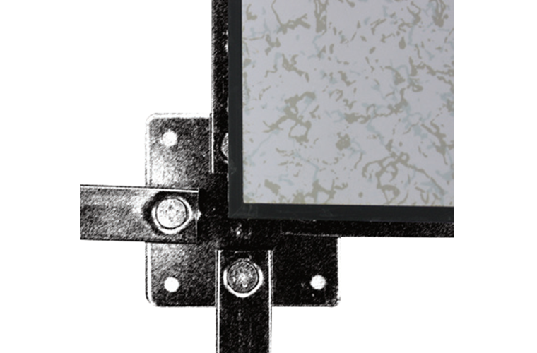
The Stringer Grid understructure system shall consist of a pedestal assembly that shall be designed to allow the mechanical fixing of hollow galvanized tube sections (stringers). The pedestal assembly shall consist of an electro-galvanized and factory assembled pedestal base and pedestal head, which shall be capable of supporting an axial load of not less than 32.00kN for a finished floor height of 150mm to 1800mm. The pedestal assembly shall be specific to the Stringer Grid system as manufactured by ALTAIR
The pedestal base should consist of a base plate 95mm x 95mm x 2.0 mm electro-galvanized steel mechanically fixed / welded to a 25.0 mm outside diameter electro-galvanized steel tube with a wall thickness of 1.6mm.
The pedestal head shall consist of a 75mm x 75mm electro-galvanized steel plate, with a material thickness of 3.0mm, welded to an electro-galvanized threaded tube of 19.0mm outside diameter.
A (two) corrosion resistant 9mm deep electro-galvanized nut(s) shall be provided and shall allow for adjustment of the pedestal assembly over a range of 50mm without rotation of the pedestal head. The nut shall be prevented from rotating by using an extra 9mm deep electro-galvanized nut or a tapered pedestal base tube.
The stringer shall be of 1.0mm thick cold-rolled hot-dipped galvanized steel section, nominally 600mm in length, designed to be mechanically fixed with a galvanized 6.0mm thick screw onto the pedestal head. The screw location on the stringer shall be countersunk.
The system shall be capable of supporting the following loads within limits and under conditions indicated, tested in accordance with “Ceiling and Interior System Construction Association”, recommended test procedure for access floors - CISCA / AF.
The panel shall be capable of sustaining a concentrated load of 3.6/ 4.5/5.6KN on a 25 mm x25mm area with a maximum top surface deflection of 2.00mm, and a maximum permanent set of 0.25mm.
The panel shall be capable of sustaining a uniformly distributed load of 16/23/33KN/m2, with a maximum top surface deflection of 1.00mm, and a maximum permanent s e t of 0.25mm.
The panel shall be capable of sustaining an ultimate load of 11/13/16kN without structurally failing and collapsing.
The panel shall be capable of sustaining an impact load created by dropping an object of 42.0/56.0/66/5 kg from a height of 36 inches without any permanent deformation exceeding 1mm.
The pedestal assembly shall be capable of withstanding an axial load of 32.0 KN and shall be adhered to the sub-floor to provide resistance against horizontal loading
Examine structural sub-floor for unevenness, irregularities and dampness that would affect the quality and execution of the work. Do not proceed with the installation until structural floor surfaces are level, clean and dry.
Concrete sealers, if used, shall be identified and proven to be compatible with pedestal adhesive to achieve an appropriate bond to the slab.
Verify dimensions on contract drawings, including level of interface such as abutting floor, ledges and doorsills.
Contact us today to talk with us about your raised access floor installation project


62de5859a8da1.jpg)


62da6697cc76a.jpg)
62da6668528cb.jpg)
62da66b1cbd6d.jpg)